Your mission: build a motor test station, compare direction and output, and explain a reliable stop rule.
Your coding goals: Complete three button-triggered motor missions: a 5-second run, a 3-second opposite-direction run and a left–pause–right sequence.
Make your prediction first. Connection and code examples stay available as optional help.
402 · MODEL 01 · 02
Make motion. Understand the stop.
Original MRT kit motor artwork · MRT3 English reference.
01Button input
→
02Pressed or released?
→
03Motor output
Predict
Will two motors mounted in opposite directions move the robot forward with the same command?
Try one idea
A DC motor changes electrical energy into rotation. The sign chooses direction; the magnitude sets output level, not a guaranteed measured speed. Mounting, battery and load affect the result.
A held-button rule and a timed sequence behave differently. In Code, specify when each mission starts, how long it runs and when both motors stop.
Explain
Identify the input, the decision and the output. A motor is an output, not a sensor.
402 · MODEL 01 · 03
Build the mechanism.
Follow one original mechanical step at a time. Use your Node board and plan its mounting. Wiring and programming are handled in the next activities.
402 · MODEL 01 · 04
Plan your connections first.
Sketch the ports you need. Open the sample when you want to compare. Switch power off before changing cables.
Show the sample connection plan
Part
Sample port
Check
DC motor
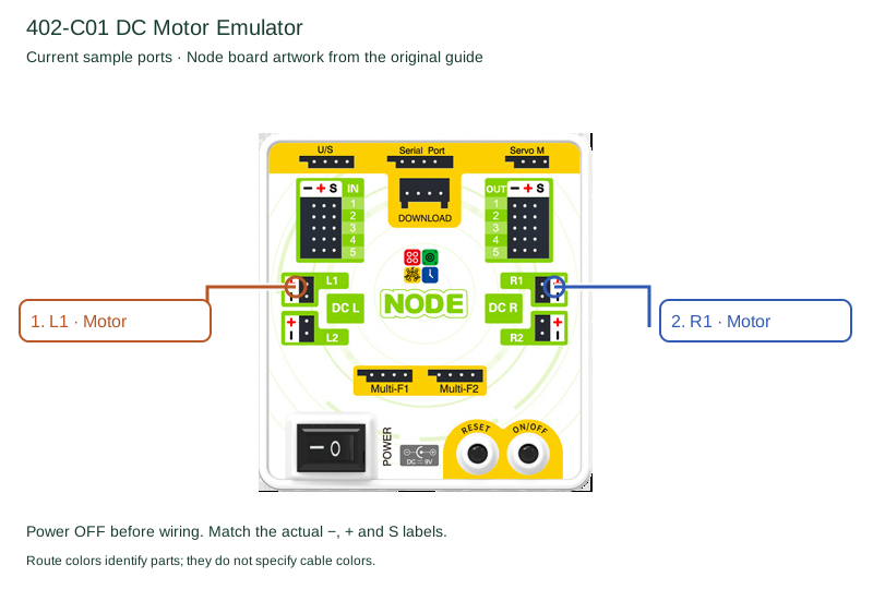
L1 and R1
Check the mounted direction of each motor.
Read the actual board labels: − is ground, + is supply, S is signal. Cable colors can vary; confirm polarity on the real connector with your teacher. Diagram highlight colors identify routes and are not a cable-color specification.
Use the 402 Node board in place of the black mainboard in the original mechanical guide. Check mounting and cable clearance before applying power.
402 · MODEL 01 · 05
Code three motor missions.
Build and test these missions one at a time. Each mission needs its own saved program. Use the board ON/OFF (START) button as the input, L1 as the left motor and R1 as the right motor.
Before coding: program start, motor direction and ports
Before the missions: start the program, then wait
These instructions are for Node USB. Upload your program, then press and release ON/OFF (START) once to launch the stored program. That launch action is not the mission trigger. Your program must begin with both motors stopped and the button released; use a new press or press-and-release for each mission. The green flag is not the board upload/start control. Bluetooth uses a separate execution flow.
Check what clockwise means
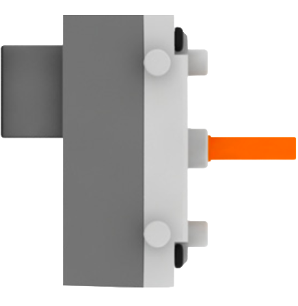
Look straight at the orange output shaft of each motor from the shaft end. Clockwise and counterclockwise refer to that view, not to the robot moving forward. A level of 50 means a 50% output command, not a measured speed in RPM.
Before Mission 1, briefly test each motor separately at +50, stop it, and record its observed direction. Use +50 for clockwise if that motor turns clockwise; otherwise use −50. Reverse that sign for counterclockwise. Record the left and right signs separately; do not assume identical signs give identical observed directions.
Record your motor direction commands before coding
Motor
Port
Clockwise at level 50
Counterclockwise at level 50
Left
L1
Record +50 or −50 after checking
Use the opposite sign
Right
R1
Record +50 or −50 after checking
Use the opposite sign
Keep the wheels or shafts clear for these motor-station tests. Use only L1 and R1; leave L2 and R2 empty. If a timed run behaves unexpectedly, switch board POWER off. Releasing START is a mission input, not an emergency stop for these timed programs.
The starter is a starting workspace, not a finished mission solution. Add the trigger, timing and stop rules yourself.
Mission 1: Press to run both motors for 5 seconds
Your task: With the program waiting and both motors stopped, press ON/OFF (START). At that press, run both motors clockwise at output level 50 for 5 seconds, then stop both motors.
Start timing when the motors start. Both motors must run together for the same 5-second interval.
Releasing the button during the timed run must not end it early. Holding the button past 5 seconds must not restart the run.
After stopping, wait until the button is released before accepting another press.
Success check: Both motors turn clockwise at level 50 for 5 seconds, then remain stopped. One press produces one run.
Mission 1 hint: plan the sequence
Wait for a new press → set both motor commands → wait 5 seconds → stop both → wait for release → return to waiting. Check the button in a repeating rule; do not put an unconditional motor command in the repeat loop.
Save as:402-c01-mission-1.sb3
Mission 2: Press and release to run opposite directions
Your task: Press and hold ON/OFF (START): keep both motors stopped. When you release it, run the left motor clockwise and the right motor counterclockwise, both at output level 50, for 3 seconds. Then stop both motors.
Detect a press first, then its release. An already released button at startup must not trigger the motors.
The 3-second timer begins on release, not on the first press.
Ignore new presses during the timed run. After stopping, require a fresh press and release before the next run.
Success check: Holding the button causes no movement. Releasing it after a press starts exactly one 3-second run in opposite directions, followed by a stop.
Mission 2 hint: plan the sequence
Wait for press → wait for release → set opposite directions → wait 3 seconds → stop both → return to waiting for a new press.
Save as:402-c01-mission-2.sb3
Mission 3: Run the motors one at a time
Your task: After a new press and release of ON/OFF (START), run only the left motor clockwise at output level 50 for 2 seconds. Stop both for 1 second. Then run only the right motor clockwise at output level 50 for 2 seconds. Stop both and wait for a new press and release.
Keep the right motor stopped during the left-motor phase, and keep the left motor stopped during the right-motor phase.
Ignore new button presses during the sequence. Do not repeat the sequence automatically.
The commanded sequence lasts 5 seconds in total: 2 seconds left + 1 second stopped + 2 seconds right.
Success check: Observe left only → both stopped → right only → both stopped, once per press-and-release. The motors never run together.
Mission 3 hint: plan the sequence
Wait for press → wait for release → left on/right stopped → wait 2 seconds → stop both → wait 1 second → left stopped/right on → wait 2 seconds → stop both.
Save as:402-c01-mission-3.sb3
Upload, test and explain
Save your mission project. Use USB Upload → Connect USB board → Build program → Upload to board → Done.
Launch the stored program once, then test the mission with a fresh button action. Repeat each test three times and record the observed direction, run time and final stopped state.
For Mission 1, compare releasing early with holding longer than 5 seconds. For Mission 2, compare a short press with a long hold before release. For Mission 3, check the stopped interval and the idle motor.
Explain the input → decision → output rule. If the result differs, change one part of the program, save and test again. Switch POWER off after testing.
The earlier physical check covered the hold-to-run reference on one unloaded board. These new timed missions are student programming tasks; their completed programs and installed mechanisms still need their own tests.
Reference only: hold-to-run program
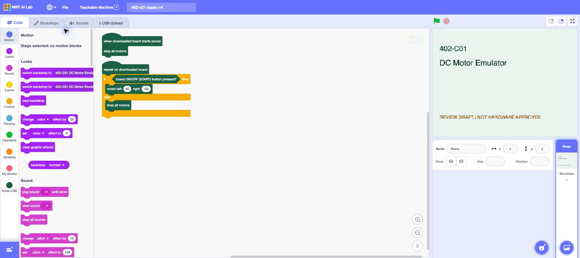
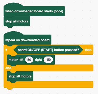
This reference is not a solution to Missions 1–3. It has no 5-second or 3-second timed run. Use it to identify the button, motor and stop blocks, then build your own mission program.
The downloaded program waits for a fresh ON/OFF (START) press and release. Press and release once to start; then hold the button to drive and release it to stop. The sample stops the motors at startup. While the board ON/OFF (START) button is held, it commands left 50 and right −50; release commands stop.
Mission 1: check both motors clockwise at level 50 for 5 seconds, followed by a stop. Compare early release and a long hold.
Mission 2: check no motion while held, then left clockwise/right counterclockwise at level 50 for 3 seconds after release.
Mission 3: check left only for 2 seconds, both stopped for 1 second, right only for 2 seconds, then both stopped.
Repeat each mission three times. Record actual timing, both observed directions, final stopped state and whether another fresh trigger is needed.
Save all three projects and explain one correction you made. Explain how the timed missions differ from the hold-to-run reference.
My evidence
Write in your learning journal, or download these notes. Notes are not submitted automatically.
Make it your own
Design a turn for a two-wheel robot. Explain both motor commands and the stop condition.
Teacher: validation scope
The content, Studio upload and physical model checks are recorded separately. A successful board transfer does not prove motor direction, sensor calibration, battery operation or mechanism load. Confirm the actual board, wiring, power and clearances for this build.
Lesson Completion
Free preview: course progress is saved only with valid course access.